Overview
This board is a custom RP2040 keyboard with onboard USB, external QSPI flash, a crystal, a BOOTSEL-style USB boot header, and a 5-row / 14-column key matrix. The examples below use the exact GPIO assignments shown in the schematic and the exact 67 populated key positions shown on the PCB.
RPI-RP2, the boot ROM,
USB path, and flash access path are likely healthy enough to proceed.
| Topic | This board | How to adapt for a different RP2040 board |
|---|---|---|
| Rows | GP0, GP1, GP2, GP3, GP4 | Replace with the actual row GPIOs used on the target PCB |
| Columns | GP5 through GP18 | Replace with the actual column GPIOs used on the target PCB |
| Diode direction | ROW2COL | Verify from the schematic; do not assume the same direction on every board |
| Boot entry | Short USB_BOOT to GND while plugging in USB | Use the board's BOOTSEL button, reset button, or boot jumper |
| Physical matrix shape | 67 used positions inside a 5x14 electrical grid | Update the QMK layout macro or KMK coord_mapping |
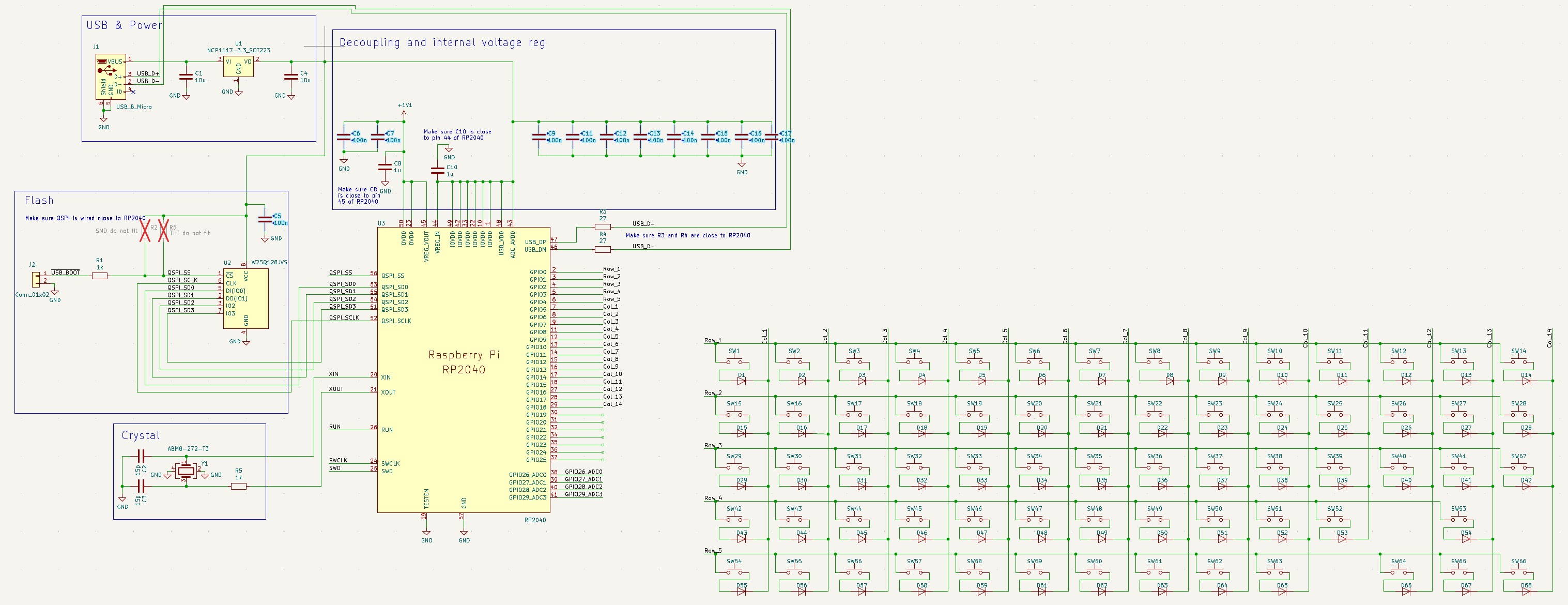
Full circuit schematic — RP2040, flash, crystal, USB, 5×14 key matrix
Entering Flash Mode
The RP2040 contains a ROM bootloader. On this board, the schematic shows a USB_BOOT header that can be pulled low to enter that mode.
- Unplug the keyboard.
- Short
USB_BOOTtoGNDon the programming header. - While keeping that short in place, plug the keyboard into USB.
- The computer should mount a mass-storage device named
RPI-RP2. - Copy a valid
.uf2firmware file to that drive. - The board should reboot automatically after the copy finishes.
RPI-RP2 drive appears: check USB power, D+ / D- routing, cable quality, regulator output,
QSPI flash soldering, and shorts around the RP2040 or crystal.
Exact Board Matrix Map
Electrically, the board is a full 5x14 matrix. Physically, only 67 of the 70 possible intersections are populated. That matters for both QMK layout macros and KMK coordinate mapping.
ROW2COL.
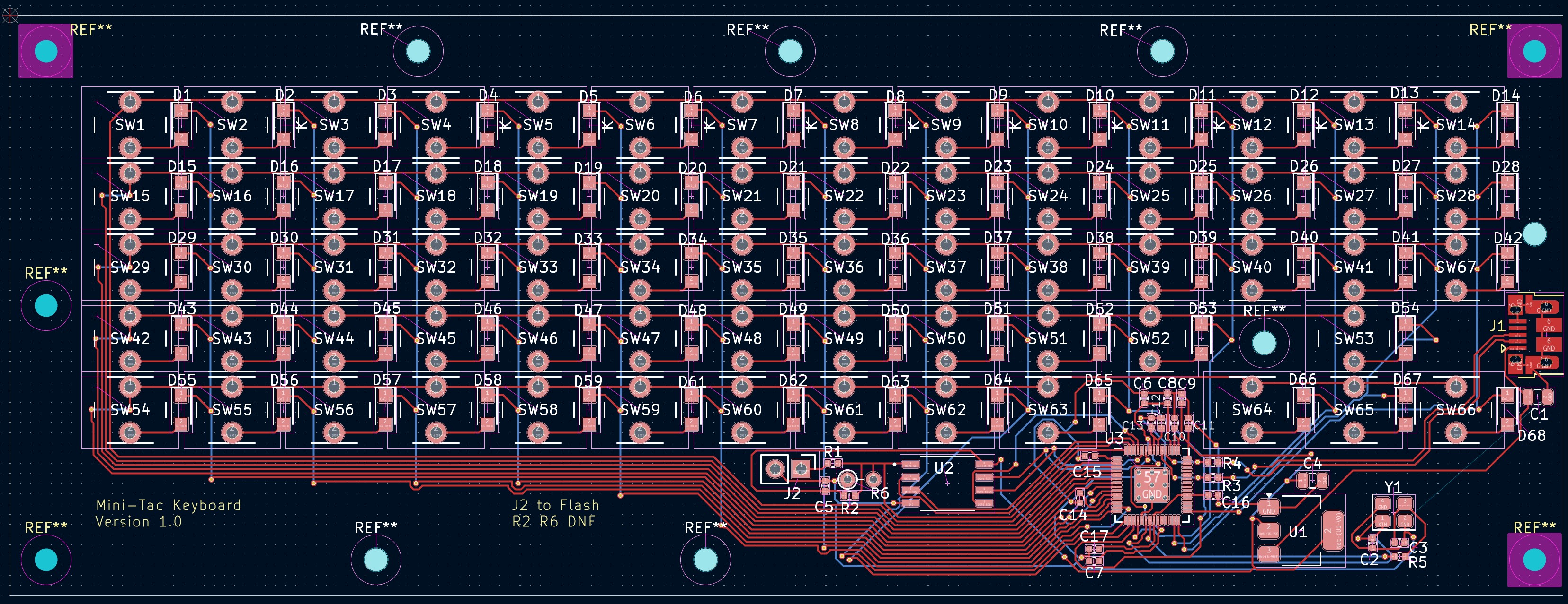
PCB layout — Mini-Tac Keyboard v1.0, 67 switches across 5×14 matrix
Key Layout
Physical layout from the keycap artwork — 67 keys across a 5×14 electrical matrix. Empty matrix positions (row 3 col 11, row 4 col 10) are shown as gaps.
Dark keys = modifier/function · Green border = Fn layer toggle · Gaps at row 3 col 11 and row 4 col 10 match unpopulated matrix positions
KMK Path — Fastest Bring-Up
KMK is the quickest way to verify that the board works as a keyboard. It runs on CircuitPython and stores configuration as editable files on the board.
When KMK makes sense
- Fast hardware validation
- Easy pin and keymap changes without recompiling
- Good early-stage development path for a brand new custom PCB
KMK install flow
- Put the board into
RPI-RP2mode. - Copy a compatible CircuitPython RP2040
.uf2to the drive. - After reboot, a
CIRCUITPYdrive should appear. - Copy the
kmk/folder onto that drive. - Create or replace
code.pywith a board-specific keymap.
Exact KMK example for this board
This example uses the exact row and column pins from the schematic and an exact coord_mapping for the 67 populated keys.
import board

from kmk.kmk_keyboard import KMKKeyboard
from kmk.keys import KC
from kmk.modules.layers import Layers
from kmk.scanners import DiodeOrientation

keyboard = KMKKeyboard()
keyboard.modules.append(Layers())

# Exact matrix pins from this RP2040 board
keyboard.row_pins = (
    board.GP0,
    board.GP1,
    board.GP2,
    board.GP3,
    board.GP4,
)

keyboard.col_pins = (
    board.GP5,
    board.GP6,
    board.GP7,
    board.GP8,
    board.GP9,
    board.GP10,
    board.GP11,
    board.GP12,
    board.GP13,
    board.GP14,
    board.GP15,
    board.GP16,
    board.GP17,
    board.GP18,
)

# The schematic shows current flowing from row -> switch -> diode -> column.
keyboard.diode_orientation = DiodeOrientation.ROW2COL

# This PCB is not a full 5x14 rectangle. There are 70 possible matrix positions,
# but only 67 switches are populated. coord_mapping lets the keymap stay in
# physical order instead of forcing three fake entries.
keyboard.coord_mapping = [
     0,  1,  2,  3,  4,  5,  6,  7,  8,  9, 10, 11, 12, 13,
    14, 15, 16, 17, 18, 19, 20, 21, 22, 23, 24, 25, 26, 27,
    28, 29, 30, 31, 32, 33, 34, 35, 36, 37, 38, 39, 40, 41,
    42, 43, 44, 45, 46, 47, 48, 49, 50, 51, 52, 54,
    56, 57, 58, 59, 60, 61, 62, 63, 64, 65, 67, 68, 69,
]

FN = KC.MO(1)

keyboard.keymap = [
    [
        # Row 1 — number row
        KC.GRV,  KC.N1,   KC.N2,   KC.N3,   KC.N4,   KC.N5,   KC.N6,
        KC.N7,   KC.N8,   KC.N9,   KC.N0,   KC.MINS, KC.EQL,  KC.BSPC,

        # Row 2
        KC.ESC,  KC.Q,    KC.W,    KC.E,    KC.R,    KC.T,    KC.Y,
        KC.U,    KC.I,    KC.O,    KC.P,    KC.LBRC, KC.RBRC, KC.BSLS,

        # Row 3
        KC.TAB,  KC.A,    KC.S,    KC.D,    KC.F,    KC.G,    KC.H,
        KC.J,    KC.K,    KC.L,    KC.SCLN, KC.QUOT, KC.INS,  KC.ENT,

        # Row 4 — 12 keys (col 11 unpopulated)
        KC.CAPS, KC.Z,    KC.X,    KC.C,    KC.V,    KC.B,
        KC.N,    KC.M,    KC.COMM, KC.DOT,  KC.SLSH, KC.UP,

        # Row 5 — 13 keys (col 10 unpopulated)
        KC.LSFT, KC.LCTL, KC.LALT, KC.DEL,  FN,      KC.SPC,  KC.HOME,
        KC.END,  KC.PGUP, KC.PGDN, KC.LEFT, KC.DOWN, KC.RGHT,
    ],
    [
        # Row 1 → F-keys
        KC.TRNS, KC.F1,   KC.F2,   KC.F3,   KC.F4,   KC.F5,   KC.F6,
        KC.F7,   KC.F8,   KC.F9,   KC.F10,  KC.F11,  KC.F12,  KC.RESET,

        # Row 2
        KC.TRNS, KC.TRNS, KC.UP,   KC.TRNS, KC.TRNS, KC.TRNS, KC.TRNS,
        KC.P7,   KC.P8,   KC.P9,   KC.PMNS, KC.TRNS, KC.TRNS, KC.TRNS,

        # Row 3
        KC.TRNS, KC.LEFT, KC.DOWN, KC.RGHT, KC.TRNS, KC.TRNS, KC.HOME,
        KC.P4,   KC.P5,   KC.P6,   KC.PPLS, KC.TRNS, KC.TRNS, KC.END,

        # Row 4 — 12 keys
        KC.TRNS, KC.TRNS, KC.TRNS, KC.TRNS, KC.TRNS, KC.TRNS,
        KC.PGUP, KC.P1,   KC.P2,   KC.P3,   KC.PSLS, KC.VOLU,

        # Row 5 — 13 keys
        KC.TRNS, KC.TRNS, KC.TRNS, KC.TRNS, KC.TRNS, KC.TRNS, KC.TRNS,
        KC.TRNS, KC.MPRV, KC.VOLD, KC.MPLY, KC.MNXT, KC.MUTE,
    ],
]

if __name__ == '__main__':
keyboard.go()coord_mapping.
QMK Path — Production-Style Starter Pack
QMK is the better choice for a custom keyboard that is expected to stay in service. It provides a more conventional keyboard firmware workflow, strong layer support, and a large ecosystem.
Suggested folder structure
qmk_firmware/
└── keyboards/
    └── handwired/
        └── mini_tac_67/
            ├── config.h
            ├── keyboard.h
            ├── rules.mk
            └── keymaps/
                └── default/
                    └── keymap.c
rules.mk
MCU = RP2040
BOARD = GENERIC_RP_RP2040
BOOTLOADER = rp2040

BOOTMAGIC_ENABLE = yes
EXTRAKEY_ENABLE = yes
NKRO_ENABLE = yes
LTO_ENABLE = yes
config.h
#pragma once

#define VENDOR_ID 0x4A43
#define PRODUCT_ID 0x6701
#define DEVICE_VER 0x0001
#define MANUFACTURER "Jaysons Workshop"
#define PRODUCT "Mini-Tac 67"

#define MATRIX_ROWS 5
#define MATRIX_COLS 14

#define MATRIX_ROW_PINS { GP0, GP1, GP2, GP3, GP4 }
#define MATRIX_COL_PINS { GP5, GP6, GP7, GP8, GP9, GP10, GP11, GP12, GP13, GP14, GP15, GP16, GP17, GP18 }

#define DIODE_DIRECTION ROW2COL

#define RP2040_BOOTLOADER_DOUBLE_TAP_RESET
#define RP2040_BOOTLOADER_DOUBLE_TAP_RESET_TIMEOUT 200U

#define USB_SUSPEND_WAKEUP_DELAY 0
#define SERIAL_NUMBER "mini-tac-67"

/*
 * The board uses external QSPI flash (W25Q128JV in the BOM).
 * If compiled UF2 files copy successfully but never boot, verify the
 * RP2040 second-stage flash setting against the actual flash part used
 * on the PCB and then add the correct RP2040_FLASH_* define here.
 */
keyboard.h
This layout macro is specific to the Mini-Tac board. It keeps the 67 physical keys while inserting KC_NO into the three matrix locations that are not populated.
#pragma once

#include "quantum.h"

#define LAYOUT_67( \
    K00, K01, K02, K03, K04, K05, K06, K07, K08, K09, K0A, K0B, K0C, K0D, \
    K10, K11, K12, K13, K14, K15, K16, K17, K18, K19, K1A, K1B, K1C, K1D, \
    K20, K21, K22, K23, K24, K25, K26, K27, K28, K29, K2A, K2B, K2C, K2D, \
    K30, K31, K32, K33, K34, K35, K36, K37, K38, K39, K3A, K3C, \
    K40, K41, K42, K43, K44, K45, K46, K47, K48, K49, K4B, K4C, K4D  \
) { \
    { K00, K01, K02, K03, K04, K05, K06, K07, K08, K09, K0A, K0B, K0C, K0D }, \
    { K10, K11, K12, K13, K14, K15, K16, K17, K18, K19, K1A, K1B, K1C, K1D }, \
    { K20, K21, K22, K23, K24, K25, K26, K27, K28, K29, K2A, K2B, K2C, K2D }, \
    { K30, K31, K32, K33, K34, K35, K36, K37, K38, K39, K3A, KC_NO, K3C, KC_NO }, \
    { K40, K41, K42, K43, K44, K45, K46, K47, K48, K49, KC_NO, K4B, K4C, K4D }  \
}
keymaps/default/keymap.c
This is a starting keymap, not a statement about the final legends or cap sizes used on the board. Replace keys as needed once the hardware is typing reliably.
#include QMK_KEYBOARD_H

enum layer_names {
    _BASE,
    _FN,
};

const uint16_t PROGMEM keymaps[][MATRIX_ROWS][MATRIX_COLS] = {
    [_BASE] = LAYOUT_67(
        KC_GRV,  KC_1,    KC_2,    KC_3,    KC_4,    KC_5,    KC_6,    KC_7,    KC_8,    KC_9,    KC_0,    KC_MINS, KC_EQL,  KC_BSPC,
        KC_ESC,  KC_Q,    KC_W,    KC_E,    KC_R,    KC_T,    KC_Y,    KC_U,    KC_I,    KC_O,    KC_P,    KC_LBRC, KC_RBRC, KC_BSLS,
        KC_TAB,  KC_A,    KC_S,    KC_D,    KC_F,    KC_G,    KC_H,    KC_J,    KC_K,    KC_L,    KC_SCLN, KC_QUOT, KC_INS,  KC_ENT,
        KC_CAPS, KC_Z,    KC_X,    KC_C,    KC_V,    KC_B,    KC_N,    KC_M,    KC_COMM, KC_DOT,  KC_SLSH, KC_UP,
        KC_LSFT, KC_LCTL, KC_LALT, KC_DEL,  MO(_FN), KC_SPC,  KC_HOME, KC_END,  KC_PGUP, KC_PGDN, KC_LEFT, KC_DOWN, KC_RGHT
    ),

    [_FN] = LAYOUT_67(
        KC_TRNS, KC_F1,   KC_F2,   KC_F3,   KC_F4,   KC_F5,   KC_F6,   KC_F7,   KC_F8,   KC_F9,   KC_F10,  KC_F11,  KC_F12,  QK_BOOT,
        KC_TRNS, KC_TRNS, KC_UP,   KC_TRNS, KC_TRNS, KC_TRNS, KC_TRNS, KC_P7,   KC_P8,   KC_P9,   KC_PMNS, KC_TRNS, KC_TRNS, KC_TRNS,
        KC_TRNS, KC_LEFT, KC_DOWN, KC_RGHT, KC_TRNS, KC_TRNS, KC_HOME, KC_P4,   KC_P5,   KC_P6,   KC_PPLS, KC_TRNS, KC_TRNS, KC_END,
        KC_TRNS, KC_TRNS, KC_TRNS, KC_TRNS, KC_TRNS, KC_TRNS, KC_PGUP, KC_P1,   KC_P2,   KC_P3,   KC_PSLS, KC_VOLU,
        KC_TRNS, KC_TRNS, KC_TRNS, KC_TRNS, KC_TRNS, KC_TRNS, KC_TRNS, KC_TRNS, KC_MPRV, KC_VOLD, KC_MPLY, KC_MNXT, KC_MUTE
    )
};
Compile and flash
# From the root of qmk_firmware
qmk compile -kb handwired/mini_tac_67 -km default

# After the .uf2 is built, put the board in boot mode and either:
# 1) drag the .uf2 onto the RPI-RP2 drive
# or
# 2) use qmk flash if the board is already in RP2040 UF2 boot mode
qmk flash -kb handwired/mini_tac_67 -km defaultBOARD = GENERIC_RP_RP2040 is used: this board is a custom RP2040 PCB, not a pre-defined RP2040 dev board with a baked-in pinout. The generic RP2040 board option is the clean base when all pins are defined manually.
W25Q128JV. If QMK compiles and copies correctly but the board will not boot the image, verify the RP2040 second-stage flash setting against the exact flash part fitted on the board.
Troubleshooting
Board will not enter boot mode
- Check that
USB_BOOTactually pulls the RP2040 boot-select path low. - Verify USB cable quality; many failures are charge-only cables.
- Measure 3.3V at the regulator output and at the RP2040 supply pins.
RPI-RP2 appears, but flashed firmware never runs
- Check the crystal and its loading network.
- Inspect the external QSPI flash orientation and soldering.
- For QMK, re-check the second-stage flash compatibility.
Some keys do not work or entire rows / columns are dead
- Confirm row and column GPIO assignments match the schematic.
- Confirm diode direction in firmware is
ROW2COL. - Check for solder bridges or open circuits on the dead row or column trace.
- Use a continuity tester from MCU pin to switch pad.
Recommended bring-up order
- Confirm the board reaches
RPI-RP2. - Flash CircuitPython and verify KMK sees keypresses.
- Once the matrix is proven, move to the QMK starter pack.
- Add a dedicated boot key or reset method in the final QMK layout.